
Choosing a Diode Laser Machine Arm is more important than comparing appearance or price alone. The arm controls reach, positioning, treatment comfort, and daily workflow. A stable design can help practitioners maintain consistent contact and reduce unnecessary adjustments.
In practical settings, examine the arm’s range of motion, locking strength, handle balance, and compatibility with the laser console. Move it slowly through typical treatment positions. Does it drift after adjustment? Does the handpiece feel heavy after several minutes? These small details often matter more than polished product photographs. Check the manufacturer’s technical documentation, warranty terms, service network, and replacement-part availability. Reliable suppliers should explain load limits and installation requirements clearly. Vague specifications deserve caution.
Material quality also affects long-term performance. Aluminum alloys may reduce weight, while reinforced joints can improve stability. However, stronger does not always mean easier to use. A rigid arm may resist movement during precise work. A flexible arm may develop unwanted play over time. This balance is easy to underestimate. It should be tested, not assumed.
Safety remains essential. Select equipment that supports the laser system’s intended operation and follows applicable local standards. Ask qualified technicians to confirm installation and maintenance procedures. User experience is valuable, but it is not a substitute for documented evidence. The best choice may not be the most expensive arm. It should be stable, ergonomic, serviceable, and suitable for your actual treatment environment. Even experienced buyers can overlook cable routing or cleaning access. That mistake can become expensive later.
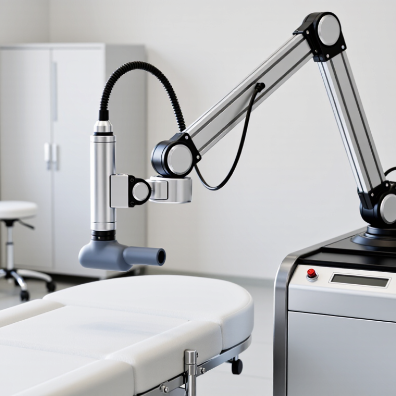
How to Choose a Diode Laser Machine Arm?
The arm must match the diode wavelength, not only the machine’s appearance. At 755 nm, melanin absorbs energy strongly, supporting precise treatment of finer, lighter hair. This wavelength demands stable beam delivery and careful cooling. Clinical reviews in Lasers in Medical Science associate shorter wavelengths with higher epidermal absorption, especially in darker skin types.
The 808 nm wavelength offers a practical balance between melanin absorption and tissue penetration. Many clinical protocols use it for common hair-removal applications. The arm should maintain consistent fiber alignment during repeated movements. A small drift can change the spot profile and reduce fluence accuracy. It happens more often than operators admit.
At 1064 nm, penetration is deeper and epidermal melanin absorption is lower. This can improve the safety margin for darker skin, when settings are selected correctly. Reports from the American Society for Laser Medicine and Surgery emphasize wavelength-specific risk control, cooling, and calibrated exposure. IEC 60825-1 also requires appropriate laser safety classification and protective design.
For a multi-wavelength platform, choose an arm with verified transmission across 755, 808, and 1064 nm. Check its bend radius, joint resistance, handpiece coupling, and internal fiber specifications. Ask for measured output data, not marketing estimates. A lightweight arm feels convenient, but excessive looseness can damage alignment. I would also test it after extended operation, because heat and repeated motion can reveal weaknesses that a showroom test misses.
How to Choose a Diode Laser Machine Arm?
Beam delivery quality should be verified, not assumed from a polished arm or bright treatment spot. Measure M² under real operating conditions, including the selected handpiece and fiber path. ISO 11146-1:2021 defines M² as a beam propagation measurement, with M² = 1 representing an ideal Gaussian beam. Higher values indicate stronger divergence and poorer focusing potential. In practical diode systems, an M² value near 1.2 is excellent, while values above 3 deserve careful investigation.
Spot size must be measured at the working distance, not only at the arm outlet. Use the 1/e² diameter and record results at several arm angles. A 10 mm spot can become visibly larger after bending, connector movement, or thermal expansion. That change affects fluence and treatment consistency. ISO 11146-1:2021 provides the measurement framework, while ISO 11554:2017 supports optical power and energy testing. Ask for raw measurement files, not marketing screenshots.
Power stability matters just as much. Record output continuously for at least 30 minutes after warm-up, then calculate variation against the average power. A practical acceptance target is within ±3%, although the correct limit depends on the application and calibration uncertainty. Test it twice. Small errors hide easily. I would also repeat the test after moving the arm through its full range. A machine may perform well on a bench, yet drift when the arm is extended. That uncomfortable gap deserves attention.
Verify beam delivery quality using M², focused spot size, and output power stability.
This non-branded engineering reference compares common beam-delivery configurations under controlled conditions. An M² value closer to 1.0 indicates better beam quality, a smaller focused spot supports higher energy density, and a lower power variation indicates more stable treatment output.
Compare Arm Reach, Joint Movement, and 360° Handpiece Positioning
Choosing a diode laser machine arm starts with usable reach, not appearance. Measure from the mounting point to the farthest treatment area. The handpiece should reach comfortably without moving the machine base. A short arm may force shoulder lifting or wrist bending. That becomes tiring during repeated procedures. However, maximum reach is not always better. An overly long arm can feel heavy and less stable. Check its working radius beside the treatment bed, not only on a product sheet.
Joint movement determines how naturally the arm follows the operator’s hand. Articulated sections should move smoothly, hold their position, and resist sudden drops. Too much looseness can affect accuracy. Too much stiffness may cause pressure on the wrist. Try slow circular movements, diagonal passes, and changes from standing to seated work. Small detail, big effect. In my experience, a joint that feels acceptable for one minute may feel frustrating after an hour.
The terminal joint should support near-360° handpiece positioning without twisting the cable or pulling the operator’s wrist. Rotate the handpiece around the treatment area and check whether the tip remains easy to control. Cable routing, locking points, and cleaning access also deserve attention. A perfect rotation range means little if maintenance is difficult. I would also test the arm with the actual handpiece, because balance can change noticeably. Operators should follow training instructions and applicable local requirements before use.
How to Choose a Diode Laser Machine Arm?
Check Medical Laser Safety Compliance with IEC 60601-2-22
A diode laser arm must guide energy accurately, not merely look stable. I check smooth movement, counterbalance, reach, and resistance at every joint. The handpiece should remain steady above uneven treatment areas. A drifting arm can change the spot position and exposure time.
IEC 60601-2-22 addresses the basic safety and essential performance of medical laser equipment. It should be reviewed with IEC 60601-1, risk-management records, and documented production testing. Ask for the exact standard edition, test scope, and independent laboratory report. A supplier declaration alone is not enough. Check the emergency stop, key control, footswitch, protective housing, beam shutter, aiming beam, warning labels, and interlock behavior. Test them physically, if possible.
The World Health Organization’s Global Patient Safety Report 2024 states that about one in ten patients experiences harm during healthcare. More than half of this harm is considered preventable. These figures are not diode-laser statistics, but they show why small control failures deserve attention. The arm’s cable routing also matters. A loose cable can catch on a trolley or pull the handpiece unexpectedly. I have learned that a polished arm can still hide weak documentation. Recheck maintenance intervals, calibration evidence, and replacement-part controls. Compliance is a process, not a sticker.
How to Choose a Diode Laser Machine Arm?
Evaluate Class 4 Protection Requirements under IEC 60825-1 and ANSI Z136.1
Choosing a diode laser machine arm starts with beam containment, not appearance. Under IEC 60825-1, many high-power diode systems are Class 4 products. Direct beams, reflected beams, and nearby skin exposure can create serious hazards. The arm should keep the beam path enclosed during normal operation. Check its joints, delivery head, protective housing, and cable routing. Small gaps near an articulated joint deserve attention.
IEC 60825-1 supports product classification and safety design. ANSI Z136.1 focuses more on workplace controls and operating procedures. A responsible evaluation should identify the nominal hazard zone, required protective eyewear, warning indicators, emergency shutdown access, and suitable interlocks. Eyewear must match the laser wavelength and optical density. General “laser-safe” glasses are not enough. Ask for measured specifications, not marketing language.
Inspect the arm while moving it through its full range. Watch for twisting, scraping, loose covers, or beam misalignment. Service access also matters. A removable panel can become a hazard if technicians bypass controls during adjustment. In practice, documentation is sometimes incomplete. That is a weakness, not a minor inconvenience. Request alignment procedures, inspection intervals, and failure responses before purchase. Local rules may add requirements beyond these standards, so a qualified laser safety officer should review the final installation.
| Evaluation Dimension | Relevant Requirement or Principle | What to Check on the Diode Laser Arm | Selection Guidance |
|---|---|---|---|
| Laser Classification | IEC 60825-1 classifies accessible laser radiation according to emission limits and foreseeable conditions of operation. Class 4 lasers can present hazards from direct, reflected, and, in some cases, diffuse reflections. | Confirm the declared class, wavelength range, maximum output, operating modes, and whether the arm can expose accessible Class 4 radiation during normal use or service. | Treat a diode laser arm as a Class 4 risk whenever the complete system permits hazardous accessible emission, even if the arm itself is only a beam-delivery component. |
| Protective Housing and Beam Containment | Class 4 systems require controls that prevent unintended access to hazardous radiation. The protective housing should withstand the intended operating conditions and foreseeable misuse. | Inspect the arm casing, joints, cable passages, handpiece connection, optical windows, and any removable covers for gaps, damage, or unintended beam paths. | Choose a rigid, opaque, serviceable arm with controlled beam routing and no exposed optical path along the outside of the articulated structure. |
| Interlocks | IEC 60825-1 uses safety features such as protective housing interlocks where removal of a housing part could expose hazardous laser radiation. ANSI Z136.1 supports engineering controls and interlocks as part of a laser safety program. | Verify that opening a relevant cover, disconnecting the arm, or removing the handpiece cannot allow uncontrolled emission. Check that interlocks are not easily defeated and that their status is monitored. | Prefer fail-safe interlocks that stop or inhibit emission and require deliberate reset after a fault or interruption. |
| Emission Indicator and Audible Warning | Laser products should provide clear indication of emission status. ANSI Z136.1 recommends appropriate warning and administrative controls for the controlled area. | Check whether visible indicators can be seen by the operator from the working position and whether audible warnings can be configured without creating confusion. | Select indicators that distinguish standby, ready, fault, and actual emission states; do not rely on a single status light hidden behind the arm. |
| Key Switch and Access Control | ANSI Z136.1 identifies access control and authorization as important elements of a Class 4 laser safety program. | Confirm that laser activation requires an authorized control, such as a key switch, coded access, or equivalent controlled function, where appropriate to the system design. | Avoid designs that allow emission immediately after power is restored or after the arm is connected without a deliberate enable sequence. |
| Emergency Stop and Remote Interlock | ANSI Z136.1 recommends emergency shutoff provisions and remote interlock capability when needed to control access or rapidly terminate emission. | Check the emergency stop location, response time, reset behavior, remote interlock connector, and whether the arm returns to a safe state after activation. | Choose a system that stops laser emission independently of normal software controls and requires a deliberate reset before re-enabling. |
| Beam Delivery and Optical Integrity | A damaged or misaligned optical path can create unexpected accessible radiation. Risk assessment should consider normal operation, alignment, cleaning, maintenance, and reasonably foreseeable faults. | Evaluate joint repeatability, fiber or internal beam-path protection, connector retention, lens security, thermal stability, and the possibility of beam leakage at articulation points. | Prefer an arm with protected optics, positive mechanical stops, stable articulation, and documented alignment and replacement procedures. |
| Handpiece and Treatment Aperture | The output aperture is a likely point of access to hazardous radiation. Protective measures must account for the intended working distance and treatment geometry. | Check aperture design, contact or distance sensors, treatment head retention, accessory compatibility, and whether the beam can be activated while the handpiece is unattended. | Select a handpiece that limits unintended emission and supports controlled positioning without requiring the operator to place hands near the beam path. |
| Mechanical Reach and Position Stability | Mechanical performance is a safety factor because unintended movement can redirect a Class 4 beam toward people or reflective surfaces. | Assess reach, joint stiffness, counterbalance, braking, drift, collision behavior, load capacity, and stability at the full extension of the arm. | Choose the shortest arm that covers the required workspace while maintaining predictable positioning and preventing uncontrolled drop or swing. |
| PPE Compatibility | ANSI Z136.1 treats laser protective eyewear as a supplemental control, not a replacement for engineering controls. Eyewear selection depends on wavelength, optical density, exposure conditions, and visibility needs. | Confirm the operating wavelength band, pulse or continuous-wave mode, maximum power or energy, required optical density, side protection, and eyewear compatibility with other PPE. | Use wavelength-specific eyewear selected through a documented hazard assessment; never select protection based only on visible lens color. |
| Controlled Area and Warning Signage | ANSI Z136.1 recommends a laser-controlled area, access restrictions, appropriate warning signs, and operating procedures for Class 4 installations. | Determine whether the arm can be used in a defined room or treatment zone with controlled entry, appropriate warning signs, and minimized reflective surfaces. | Choose an arm and installation layout that support a clearly defined controlled area and prevent beam access beyond the intended workspace. |
| Service, Alignment, and Fault Recovery | Class 4 servicing and alignment can create additional exposure hazards. Procedures should address lockout, authorized personnel, temporary controls, and verification after service. | Review service-mode access, alignment tools, diagnostic emission levels, fault logs, calibration requirements, replacement parts, and documented test points. | Prefer designs that keep alignment enclosed and provide a controlled, low-risk service mode with clear maintenance instructions. |
| Documentation and Compliance Evidence | IEC 60825-1 addresses laser product safety and classification. ANSI Z136.1 provides guidance for safe use, including roles, training, controls, and hazard evaluation. The standards serve different purposes. | Request the applicable classification information, risk assessment, user manual, interlock circuit description, inspection schedule, warning labels, and test records. | Do not rely on a generic “Class 4 compliant” statement; verify the complete machine, arm, accessories, and installation against the applicable local requirements. |
| Overall Selection Decision | A safe choice combines engineering controls, administrative controls, training, maintenance, and a documented hazard assessment. | Score the arm against containment, interlocks, emergency controls, mechanical stability, service safety, PPE compatibility, and installation requirements. | Select the arm that provides the strongest controllable safety architecture while meeting the required reach, ergonomics, treatment accuracy, and maintenance needs. |
The arm must transmit the selected wavelength consistently. Wavelengths of 755, 808, and 1064 nm behave differently in tissue. A mismatched arm can reduce beam quality and treatment consistency. Appearance proves very little.
The 755 nm wavelength is strongly absorbed by melanin. It can support precise treatment of finer, lighter hair. The 808 nm wavelength balances melanin absorption and tissue penetration. The 1064 nm wavelength penetrates deeper and absorbs less epidermal melanin. Settings still require care.
Confirm verified transmission across all selected wavelengths. Check the bend radius, joints, fiber, and handpiece connection. Request measured output data instead of promotional estimates. Test the arm after extended operation. Heat reveals weaknesses.
Measure the beam under real operating conditions. Include the actual handpiece and complete fiber path. Check M², spot size, and power stability. An M² value near 1.2 is excellent in practical diode systems. Values above 3 need investigation.
Spot size affects fluence and treatment consistency. Measure it at the working distance, not only at the arm outlet. Record the 1/e² diameter at several arm angles. A 10 mm spot may enlarge after bending or connector movement. Small changes matter.
Record output continuously for at least 30 minutes after warm-up. Compare variation with the average power. A practical target is within ±3%, depending on calibration uncertainty. Repeat the test after moving the arm fully. Bench results can mislead.
Measure from the mounting point to the farthest treatment area. The handpiece should reach comfortably without moving the machine base. Test beside the treatment bed, not only from a product sheet. An overly long arm may feel heavy and unstable. More reach is not always better.
Joints should move smoothly and hold their position. Test circular movements, diagonal passes, and seated operation. Loose joints can reduce accuracy. Stiff joints may strain the wrist. Try longer sessions. One minute is not enough.
It can improve control around curved treatment areas. Rotate the handpiece without twisting the cable or pulling the wrist. Check cable routing, locking points, and cleaning access. Test the actual handpiece because balance may change noticeably. Rotation alone solves nothing.
Choosing the right Diode Laser Machine Arm requires careful attention to both optical performance and clinical usability. First, confirm that the arm is compatible with the intended diode wavelengths, including 755, 808, and 1064 nm, and verify beam delivery through M² value, spot size consistency, and power stability. These factors help maintain predictable energy distribution and treatment accuracy. The arm should also provide sufficient reach, smooth joint movement, and flexible 360° handpiece positioning so operators can work comfortably across different treatment areas.
Safety and compliance are equally important. Evaluate whether the system meets the relevant medical laser requirements of IEC 60601-2-22, including protective design and operational controls. Because diode laser systems may involve Class 4 hazards, review safeguards according to IEC 60825-1 and ANSI Z136.1, such as beam containment, emergency stops, warning indicators, protective eyewear, and controlled access. A well-matched arm should combine reliable optical delivery, ergonomic movement, stable operation, and comprehensive safety provisions.

Venus Laser